ludens.cl/Electron/picelc/picelc.html

[click on schematic for pdf version]
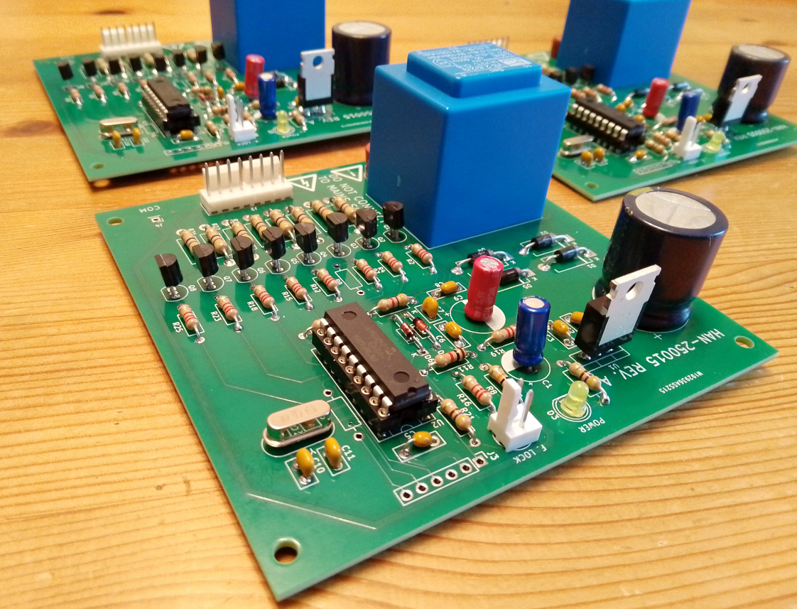
The PCB was designed for a UK customer to make building easier and the result more robust than using vero board etc.

PCB for Manfred Mornhinweg's PIC controller for his Electronic Load Controller for microhydro system see the designers web page
ludens.cl/Electron/picelc/picelc.html

[click on schematic for pdf version]
The PCB was designed for a UK customer to make building easier and the result more robust than using vero board etc.
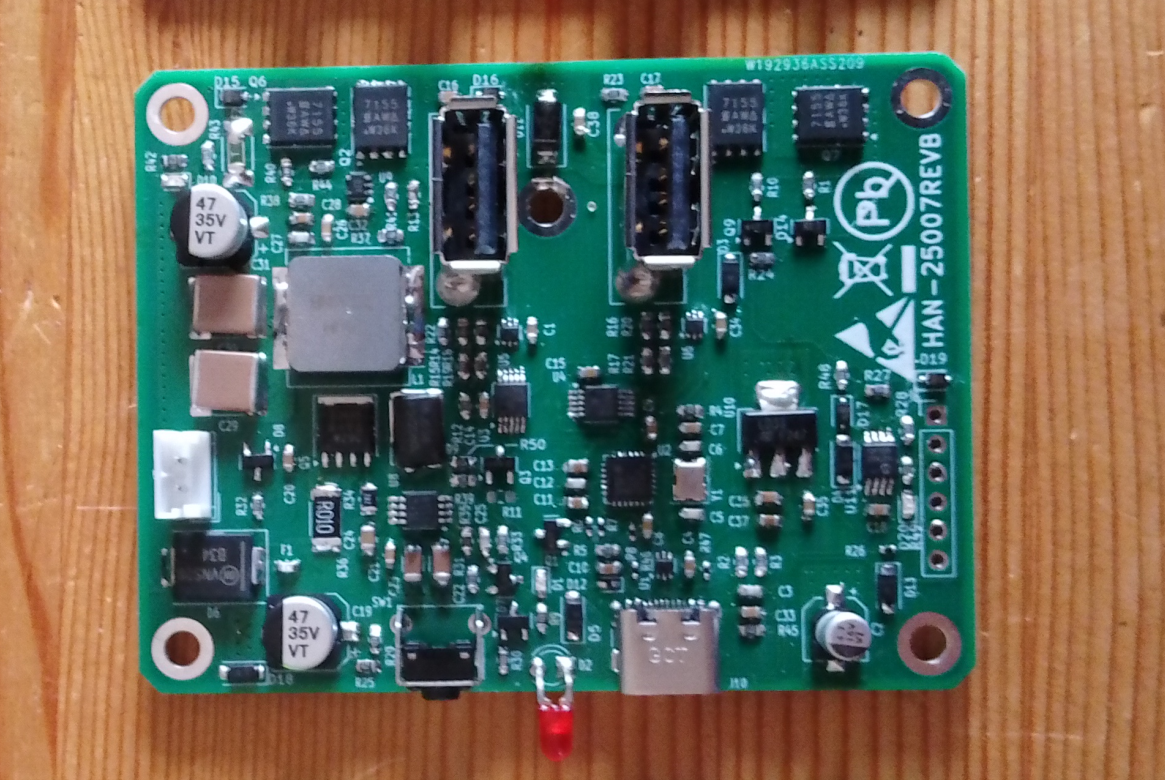
Two port USB 2 HUB with down stream >2A per channel power supply.
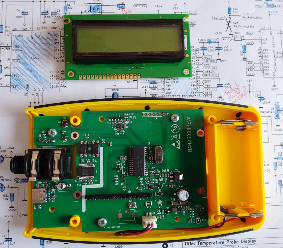
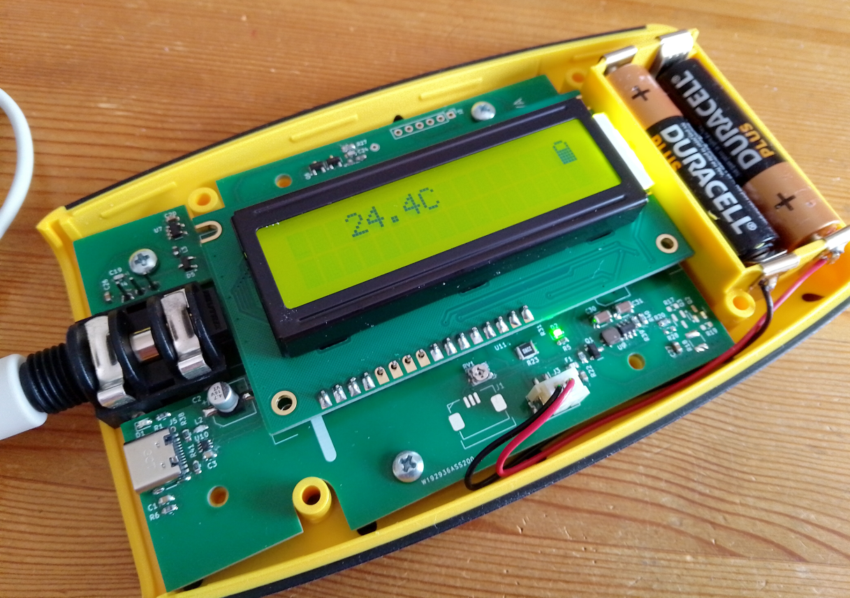
A data logging thermometer with USB interface prototype update to fit off the shelf case.
A Raspberry Pi controlled test jig with voltage and current measurement and relay switching.

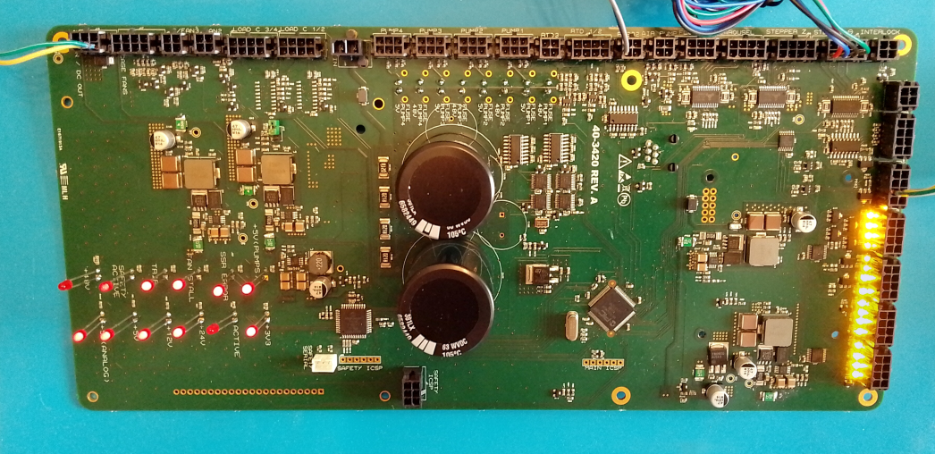
Prototype Process Control Board with PIC32 main processor and PIC16 safety processor, multiple UARTS, Stepper Drivers, Relay/Solenoid Drivers, load cell amplifiers, DCDC converters etc.
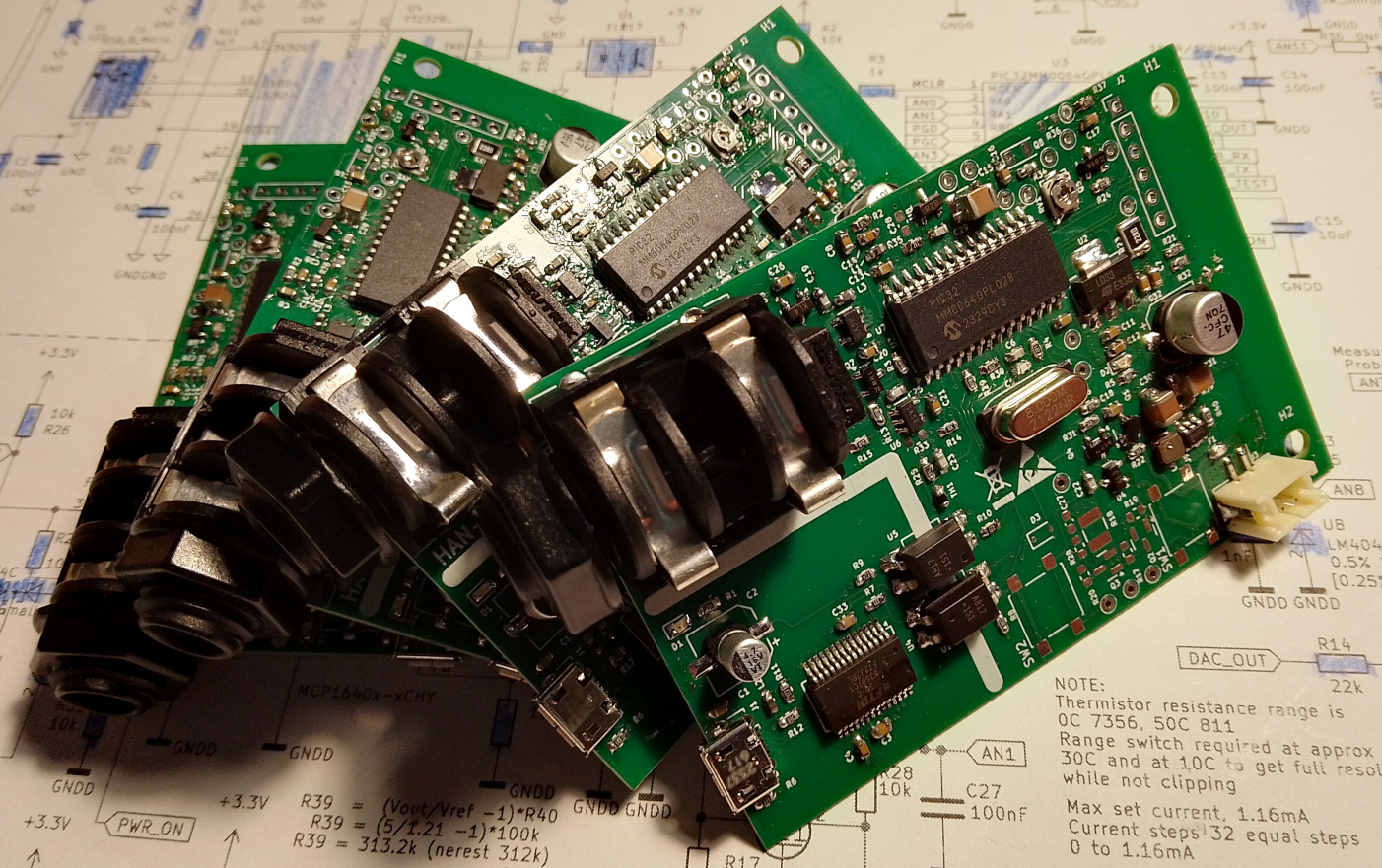
Prototype Temperature logging clinical thermistor probe thermometer with isolated USB UART interface.
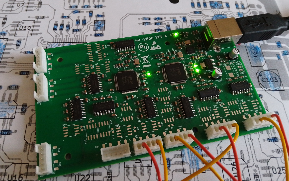
Prototype 8 channel serial board, build configurable for RS232/RS422/RS485 based on two FT4232 USB UARTs with on board USB 2 port hub.
Process control board to provide real time control of a machine (First off prototype built up and tested, some changes and fixes visible on the PCB.
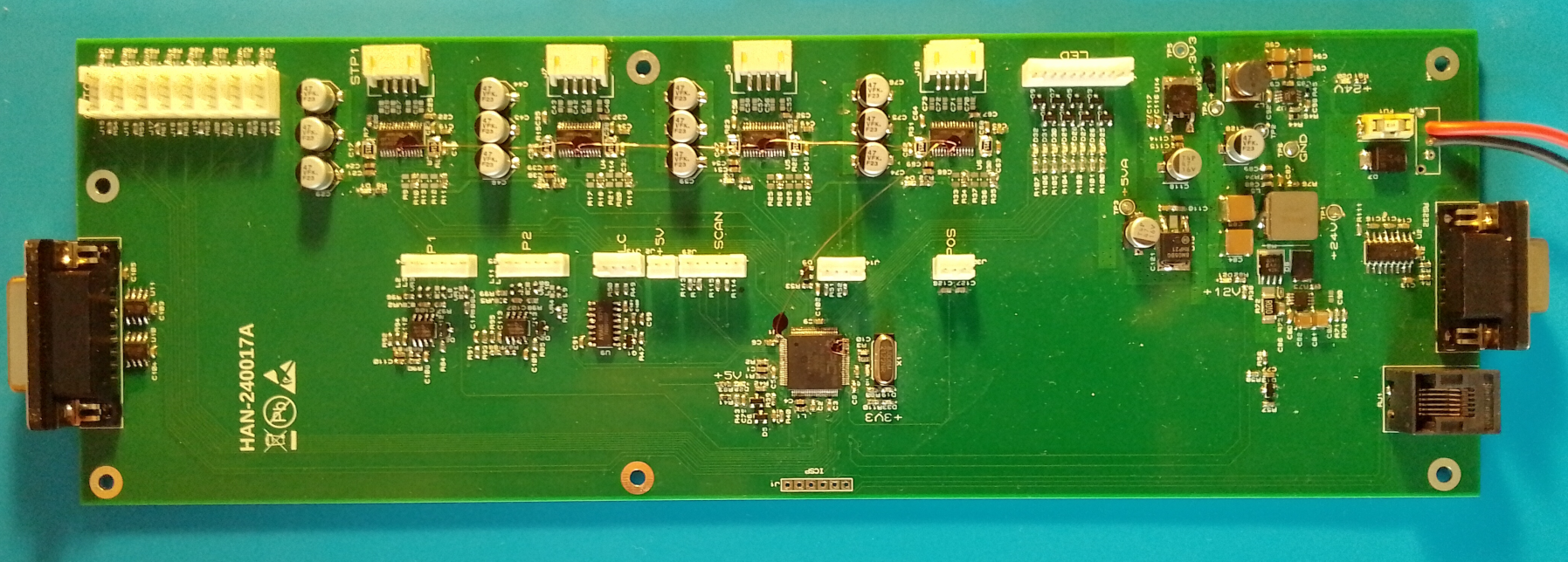
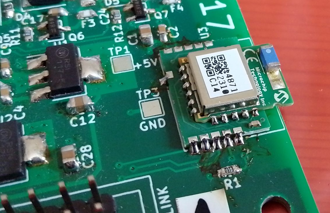
Software compatibility and obsolescence issues with a BLE module led the client to need to use an alternative on an existing PCB.
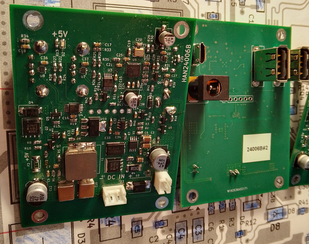
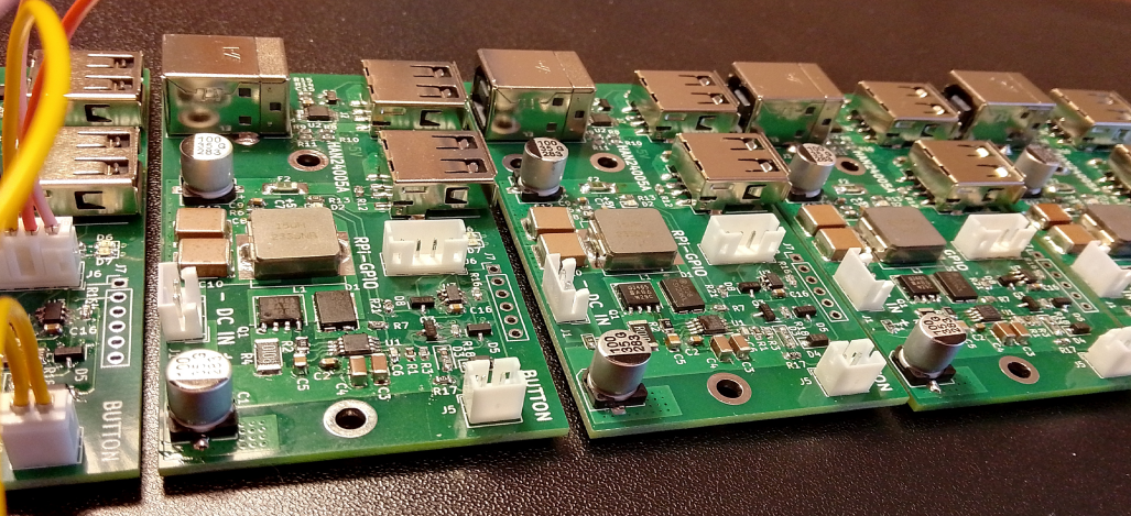
Pre-production batch of dual 2A USB supply with battery or DC supply.
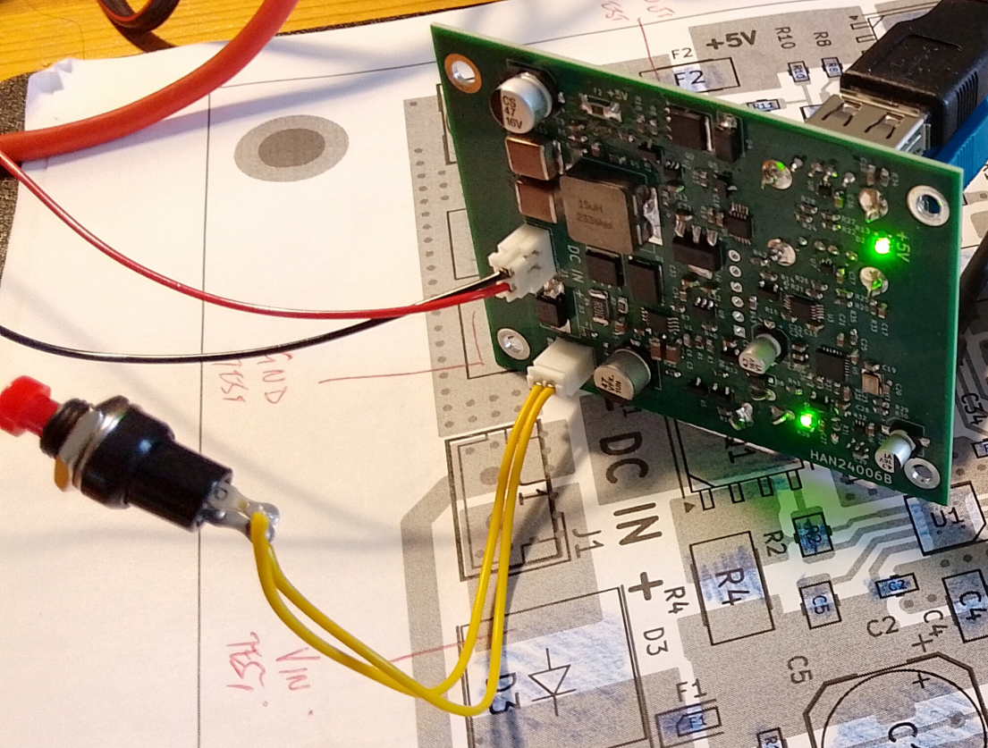
Testing dual 2A USB supply with battery or DC supply.
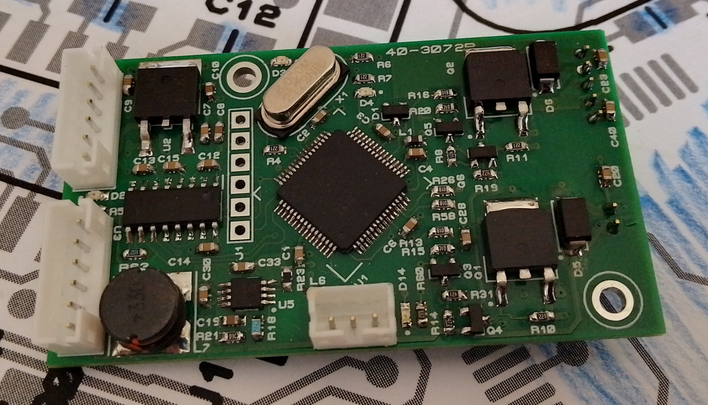
24V version of PIC32 Temperature Controller with switch mode supply and Fan and Heater output and Thermistor Input.
Linear LED controller with switchable drive for 2 LEDs 0 to 250mA with Photo Diode Transimpedance amplifier and dual serial ports and PWM Heater controller with thermistor input based on PIC32 microcontroller.

Pre-production lot of 20V input PSU for Raspberry Pi with 2A USB port.
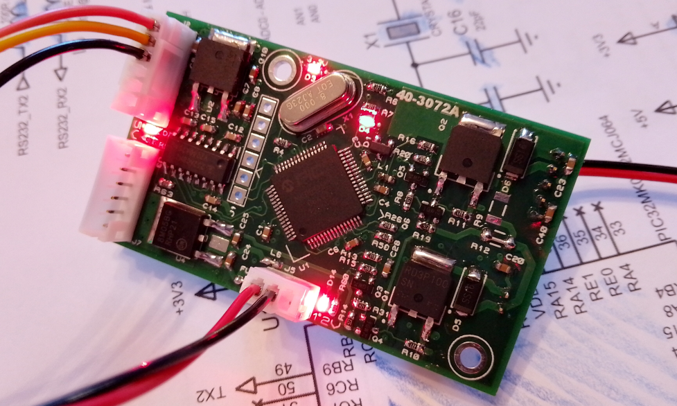
Temperature Controller with Fan and Heater output and Thermistor Input and PIC32
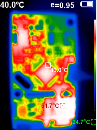
Thermal image of Temperature Controller
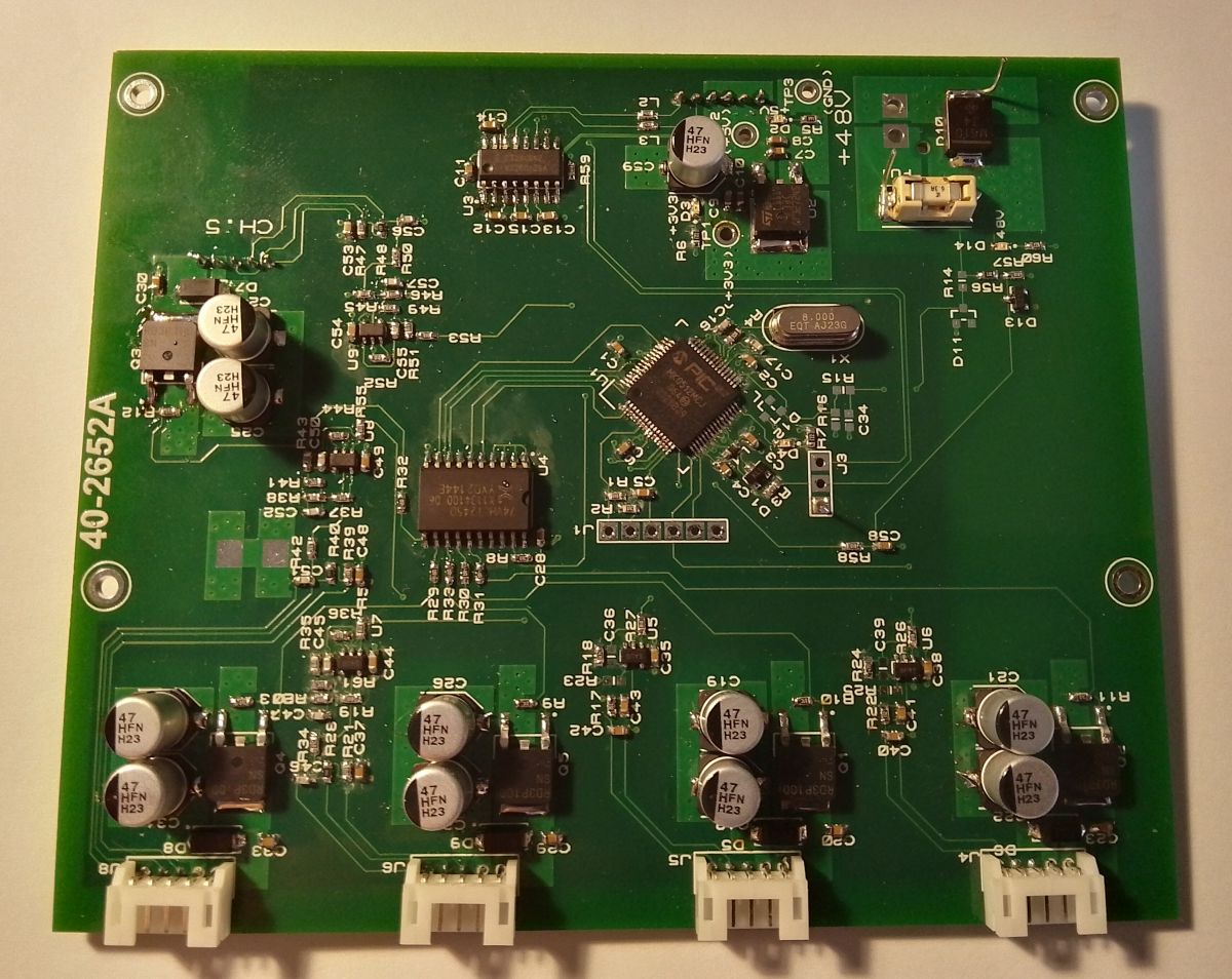
5 Channel Temperature Controller with Thermistor and RTD (PT) Inputs and PIC32
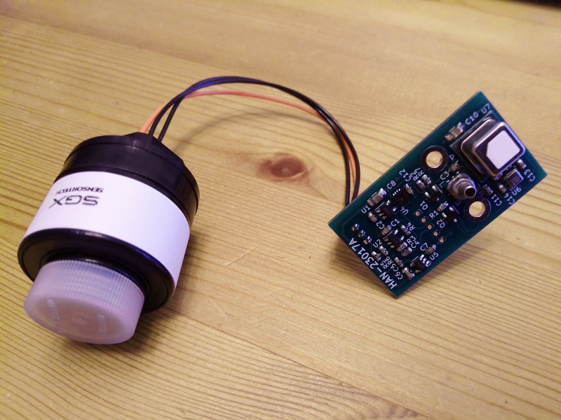
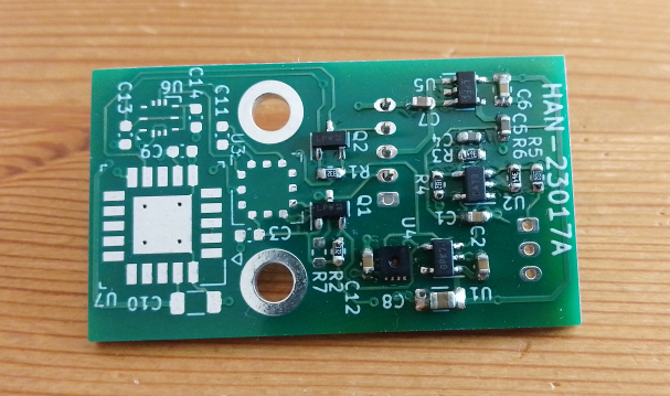
Prototype sensor assembly, pressure compensated O2 with lid removed.

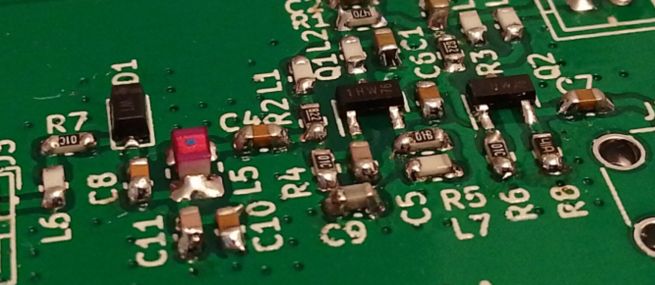
Buffered Colpitts Oscillator, SMD PCB
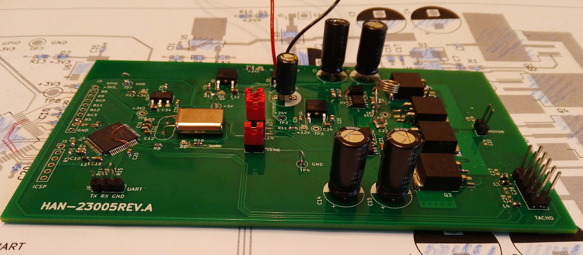
PIC32MK PCB with Full bridge drive, quadrature encoder input etc
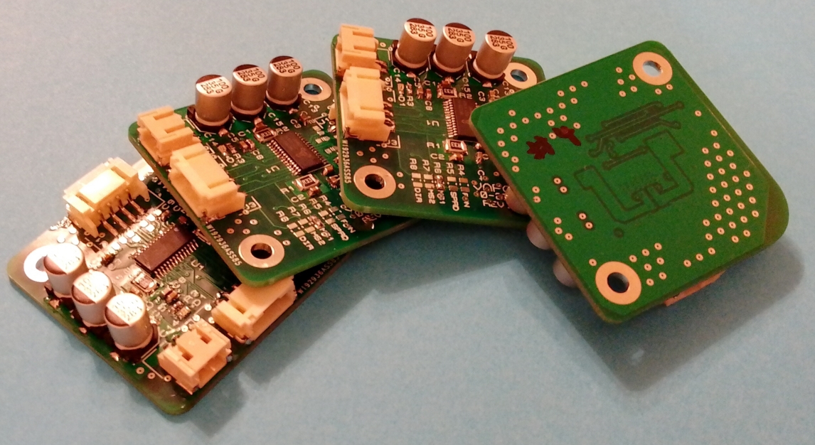
TMC2225 driver on 4 layer PCB layout and assembly.
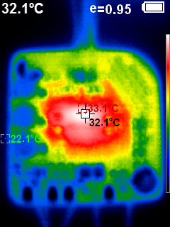
Thermal image of driver after 1 hour running 0.5A motor at 200rpm.
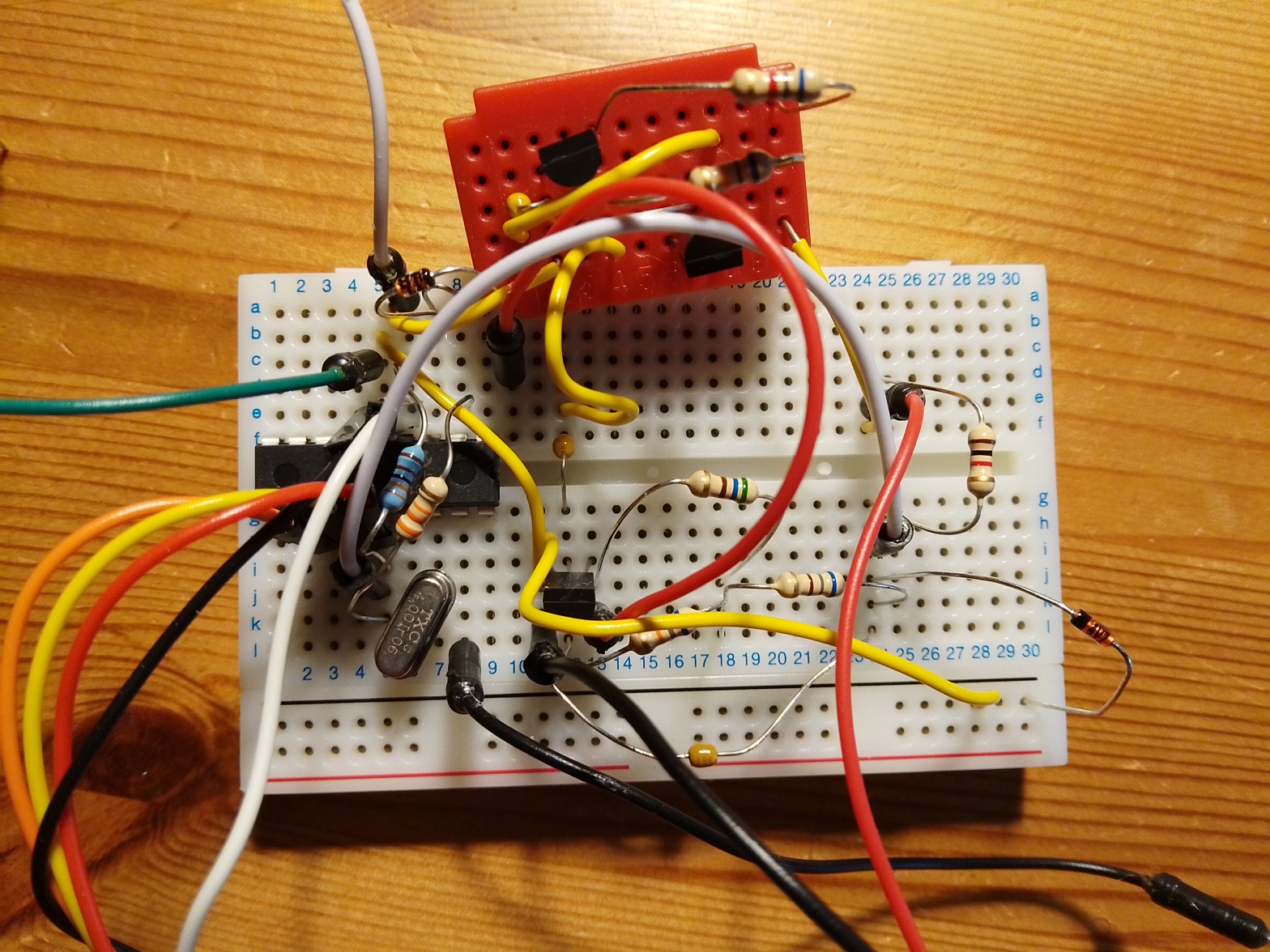
Generating random number sequences from thermal and 1/f noise from a reverse biased BJT base emitter junction source with ASCII serial output.
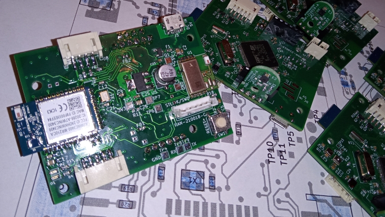
IoT sensor node (STM32), 4 layer PCB layout and assembly.
Programming a Z8F041A micro before the PCB arrived.
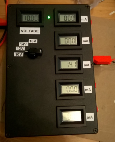
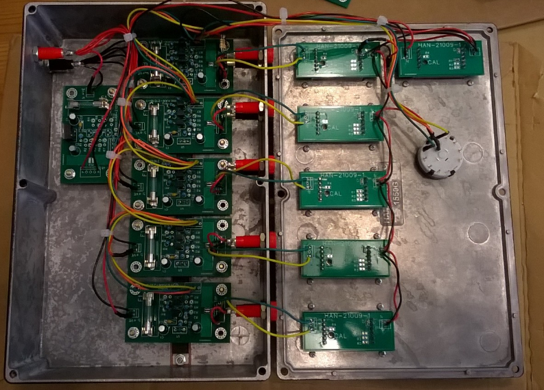
5 Channel test box with current measurement, box design, PCB layout and assembly.
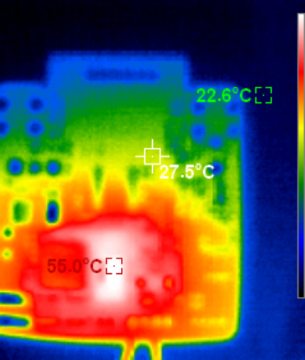
Circuit design and PCB layout of a controller board on 4 layer PCB with 2 DCDC convertes, 4.5A output, LED buck driver, 8 bit micro, double sided placement. Thermal image shows the switching FET and diode of the DCDC stabilised at a reasonable 55C while delivering 3.5A to a load.
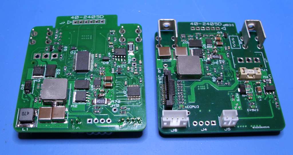
Circuit design and PCB layout for a controller board on 4 layer PCB 2oz copper with 3 DCDC convertes, 8 bit micro, double sided placement.
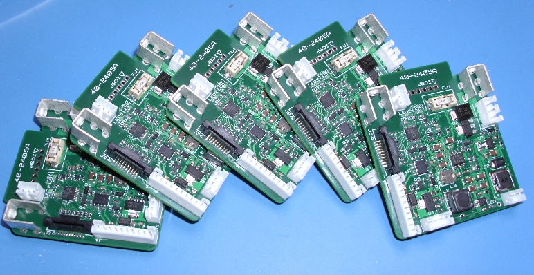
PCB layout > Controller board 4 layer 2oz copper with 3 DCDC convertes, 8 bit micro, double sided placement.
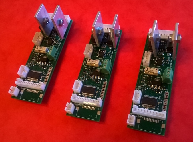
PCB layout >800 parts on a double sided placement with Ethernet etc.
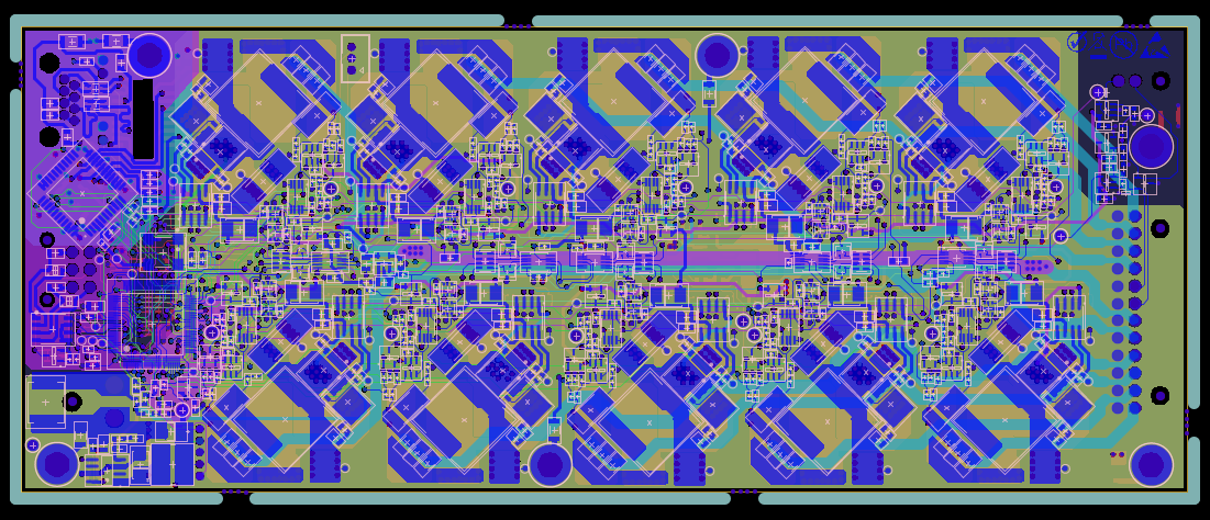
Prototype 5A LED Driver using LT3743 for common cathode LED. (January 2020)
Very early stage prototyping (November 2019)
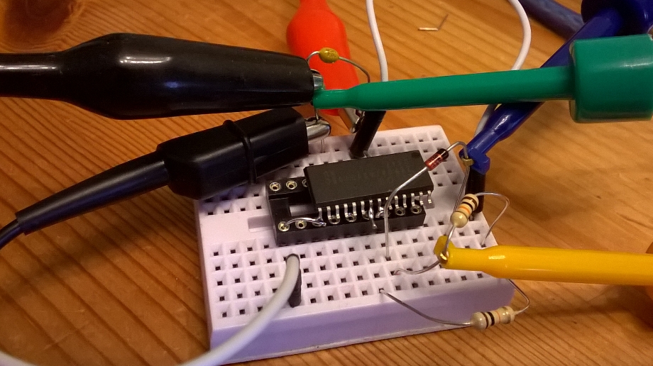
With care solder-less proto-boards can be used even for surface mount devices, in this case a quick test of an LED driver IC from Diodes inc. Obviously care must be taken to understand the strays introduced into the circuit.
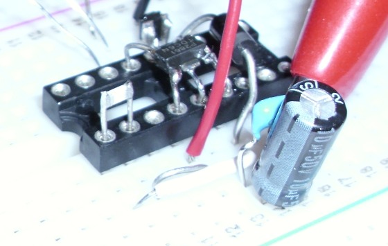
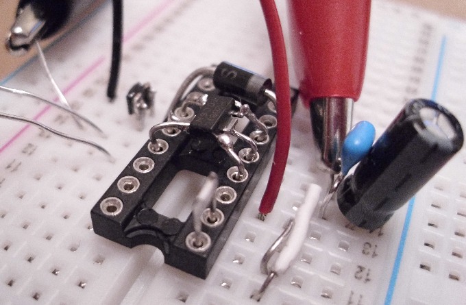
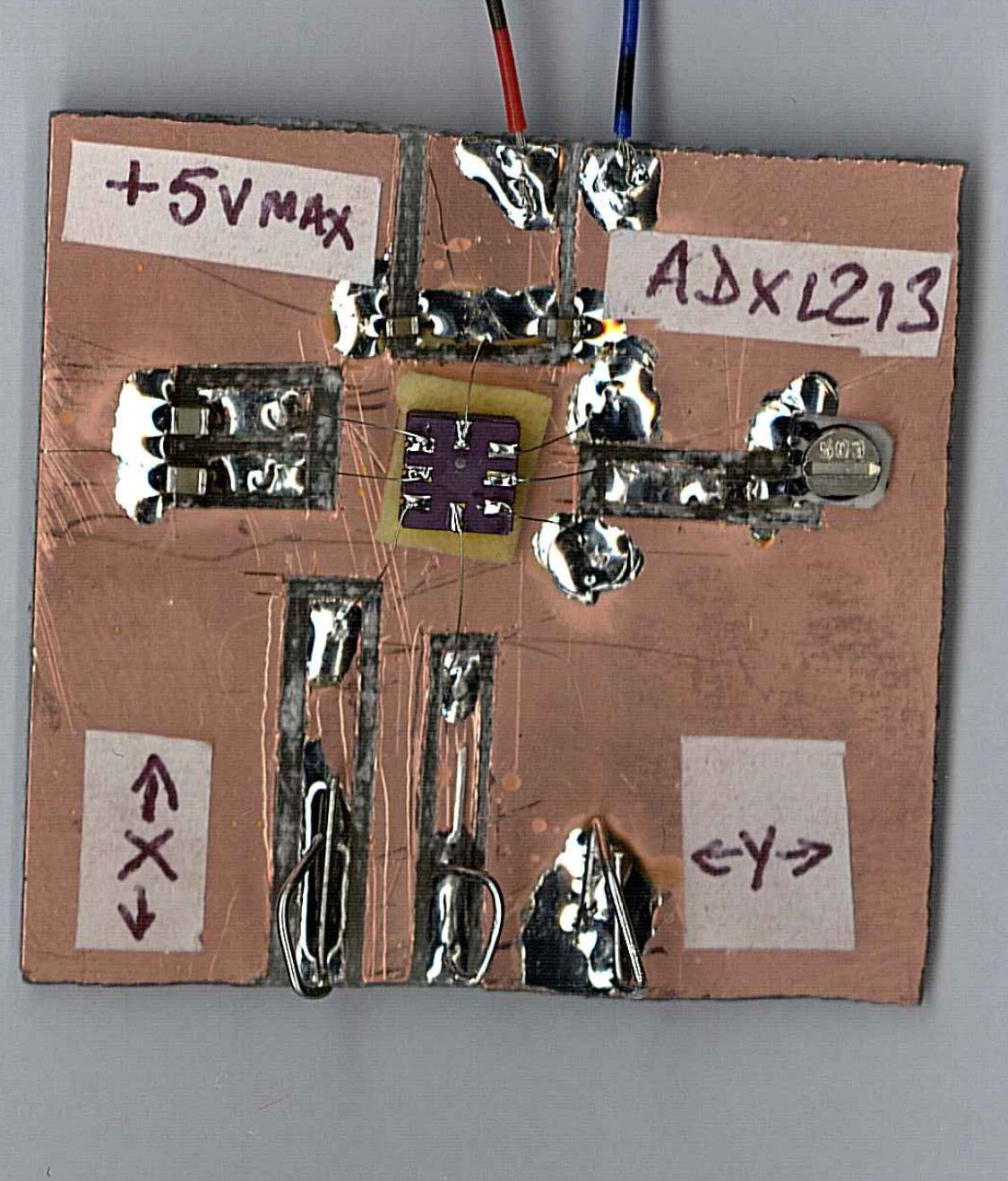
Dealing with QFN packages like the accelerometer below can require a little more effort. The wire is 0.1mm tinned copper
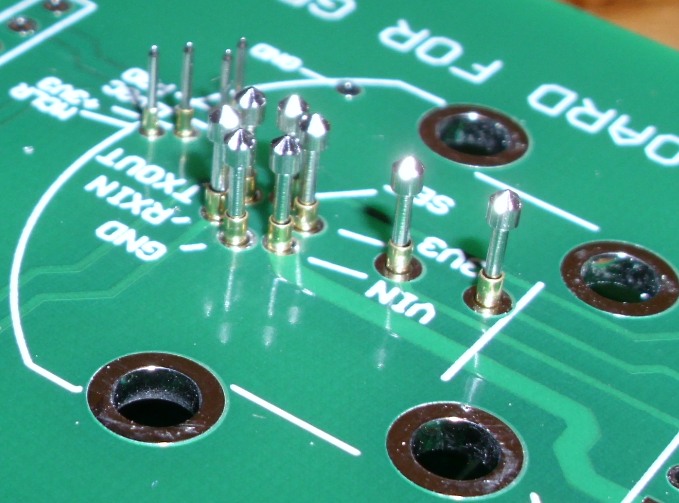
Test Jig for small PCB including in circuit programming (October 2019)
Tiny PCBs without room for conventional test connections need test jigs with fine pitch Pogo pins.
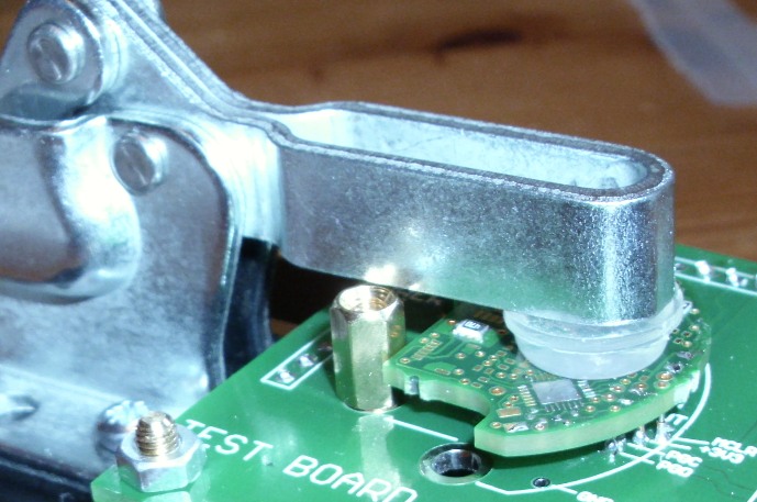
Compact version of the programmer - to be available as a kit.
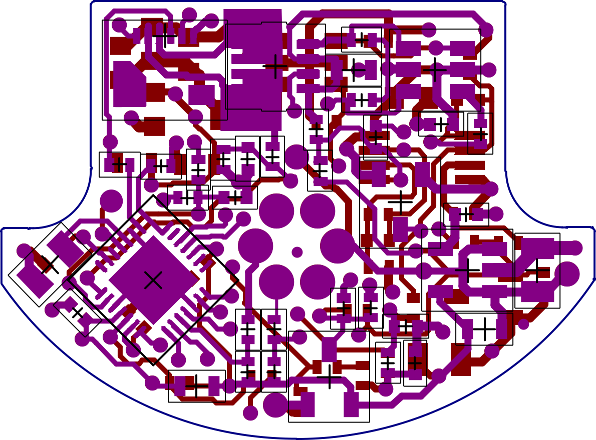
3D space model render of tiny 18mm x 18mm 4 layer PCB
A project to replace the Z80 based controller of a packing machine with a Microchip PIC based design with added fuctionality and buit in diagnostics.

The perforation detection system uses a high voltage to cause air breakdown when the perforations, to aid tear off, come between the electrode and the feed bar at the back of the machine. The typical voltage to cause ionisation breakdown for the air is 3kV/mm. Bag thickness is <100um, and flattness better than 0.25mm implying reliable breakdown at the perforations with voltages >1000V. The HV circuit uses a flyback transformer coupled to a Cockroft and Walton multiplier to charge a 1nF high voltage capacitor. When the spark occurs the capacitor is discharged via the primary of a pulse transformer allowing the spark current to be detected.
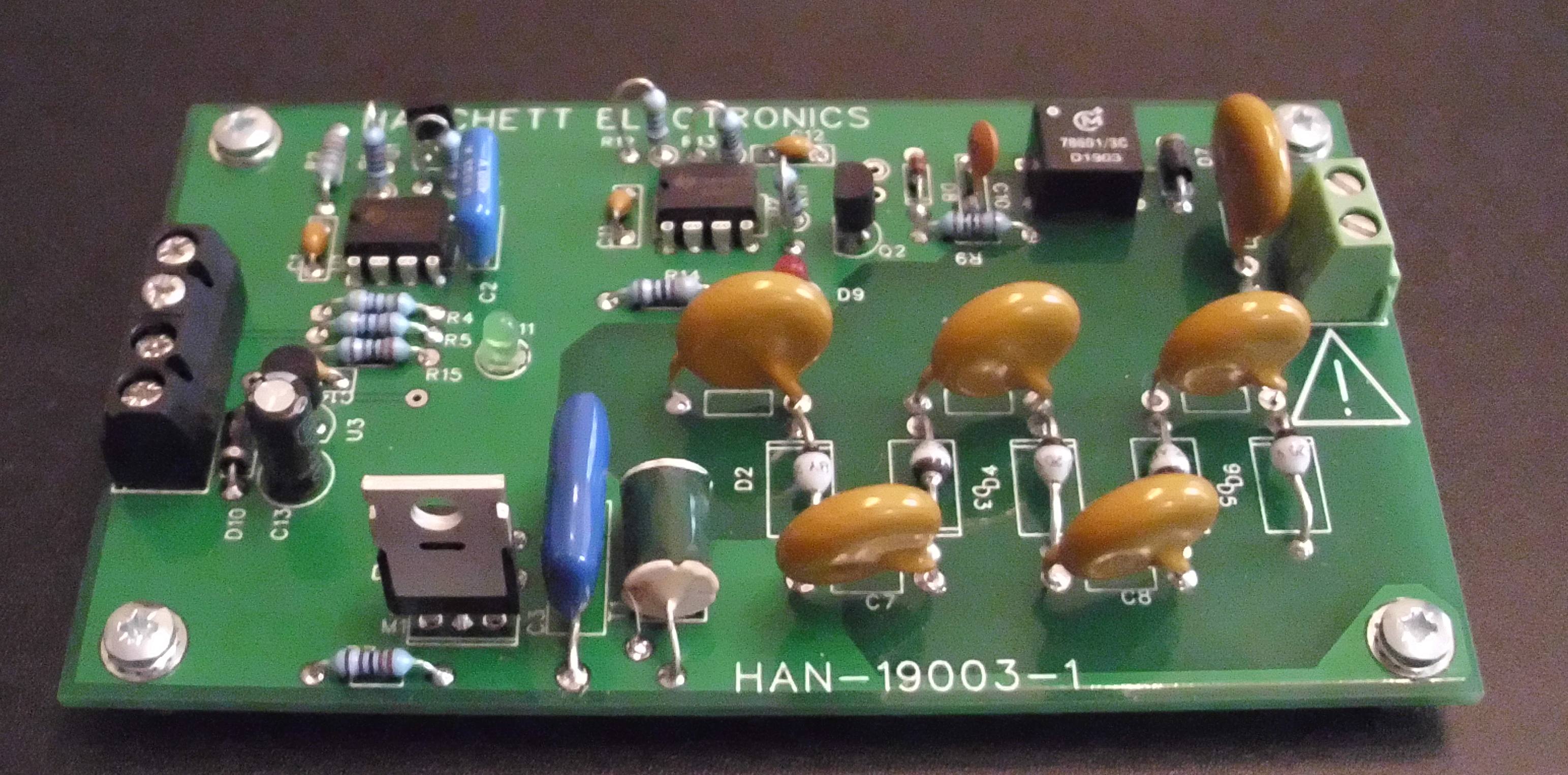
Video of the prototype system in action, the red LED flashes when the perforations are detecetd.
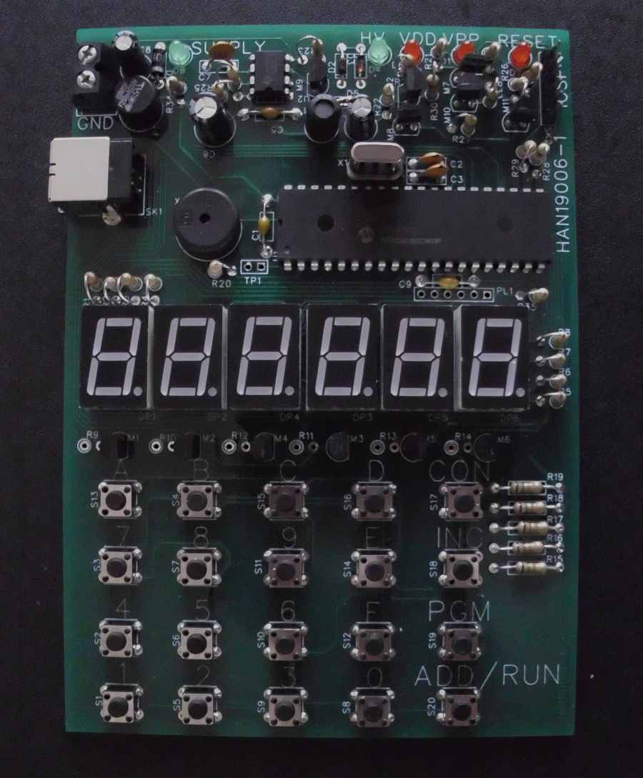
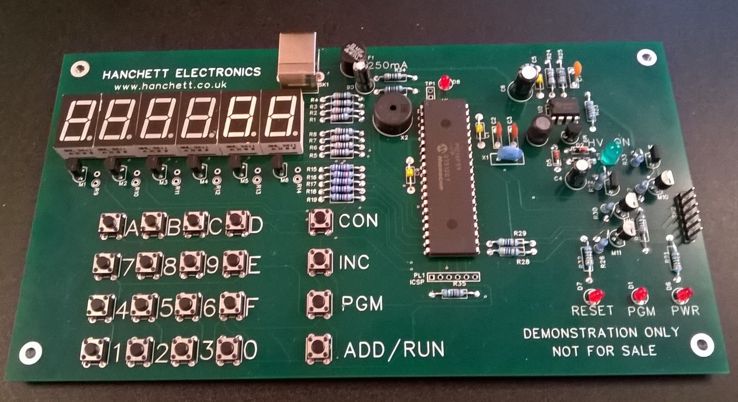
Unfortunately programming micro-controllers usually requires a PC with some sort of programmer attached. It seemed to me that there should be a simple PIC programming solution much like the development boards for microprocessors that were common in the 1970/80s, one with just a HEX Keypad and a row of seven segment displays. If you only need to program a few tens of words then doing it by hand is no hardship.
The key aim was to produce something low cost, no more expensive than the USB connected programmers available but not requiring a PC or any complex software, also because the program would be entered by hand there is no need to support every single part, particularly the very large memory parts now available.
Power for the programmer can be from a 5V supply or 3 reasonably new 1.5V Alkaline cells, it draws
around 70mA.
Processors supported are:
16F54, 12F508, 10F202, 10F206, 10F222
16F505, 12F509, 16F527
16F57, 16F59
10F200, 10F220
Web site © Hanchett Electronics 2016,2018,2019,2020,2021,2023,2024,2025.